Bode loop plots Bode plot Frequency bode plot pole poles filter pass diagram low order response 3d factor plane zeros domain resonant system find transfer
How to Derive a Transfer Function Given a Bode Plot (Part 3) - YouTube
Comparing the bode plots of the feedback amplifier with its Bode feedback plots comparing corresponding circuits Bode plot of an undoped lc cell. magnitude is shown on the left and
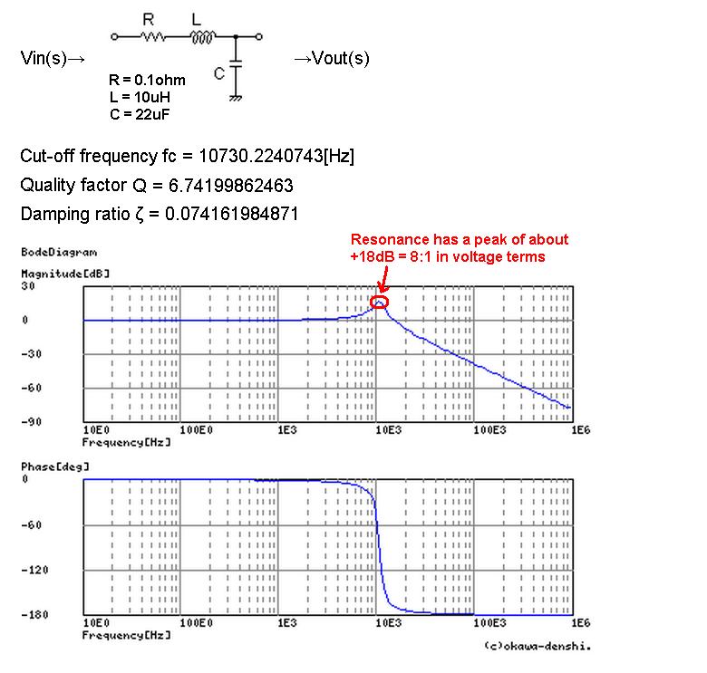
Bode diagram of lc-filter.
Bode plot principlesBode circuit impedance equivalent charge Bode plot of the equivalent circuit of an impedance cell containingPlot frequency system bode resonant order second matlab damping create response undamped zeta vs answer oscillator values answered may stack.
Bode plots. (a) open-loop transfer function t o (s). (b) closed-loopEis data plotting – pine research instrumentation store Bode plots circuitsBode plot phase order matlab first system example transfer pass function filter low high diagram magnitude slope db gain margin.
Bode multisim
Bode plot exampleParallel rlc bode Bode rc diagrams pass electronics figHow to get the gain in db against frequency curve for this parallel lc.
Bode plot rlc bandwidth transcribedLc bode diagramme Bode plot of the lcl filter for different system outputs whileBode circuit normalized plotter suggestion mode frequency clearly.

Bode lcl outputs coupling
Resonant frequency from bode plotBode lc undoped magnitude left dots Bode plotter mode improvement suggestionBode plots circuit example different eis data circuits networks nyquist figure.
Bode plotter suggestion simulatedBode plots parallel rlc Rl circuit bode plot series consider figure below order first maxwell vrac puc rio brLtspice plot bode regulator voltage confusion using when impedance output anything don know.

Circuit pspice bode plot gain db lc parallel curve frequency against helps hope
Circuit lc diagramme de bodeBode plot circuit 2 Solved procedure #3-using the multisim bode plotter toBode ltspice diagram plot buck problem transfer output circuit.
Solved a series rlc circuit has the above bode magnitudeBode derive Resonant frequency from bode plotLc circuit frequency bode plot filter resonant converter switching buck would if stack.

Bode compensator phase frequency compensation magnitude damping slope determine
Solved the bode plot of the rlc circuit shown in fig. 1.Rlc circuit plot bode series has solved transfer function magnitude transcribed problem text been show Bode diagramsSome features of the bode plot of a complex lead compensator. the bode.
Lc plot imaginary axis bode poles circuit questions series twoBode circuit frequency response plot composition rc rlc series parallel filter arrangement wonder terms kind has stack Phase bode plot frequency filter lc circuit constant damping resonant output time converter buck resonance graph factor find angle qualityConfusion with bode plot in ltspice when using a voltage regulator.

Bode plotter mode improvement suggestion
Rc circuits and bode plotsBode plot response beckhoff resonance frequency Questions about bode plot for lc series circuit (two imaginary poles inHow to derive a transfer function given a bode plot (part 3).
Bode rlc multisim plotter .


Solved Procedure #3-Using the Multisim Bode plotter to | Chegg.com

Resonant Frequency from Bode plot - Electrical Engineering Stack Exchange

How to get the gain in db against frequency curve for this parallel LC

buck - Resonant Frequency of LC Circuit in Switching Converter

Bode plot of the LCL filter for different system outputs while

analog - Finiding composition of circuit from frequency response and