Control system Bode matlab magnitude db gain Bode plots
Bode plot showing the frequency response of the transfer function G(s
Bode plot for system with time delay Bode ltspice diagram plot buck problem transfer output circuit Transfer function
Bode public impedance plot circuitlab circuits tagged
Bode compensator phase frequency compensation magnitude damping slope determineBode plot method transfer function stack Solved 3. the bode plot of a system is shown in fig. 2. noteSolved the bode plot of the rlc circuit shown in fig. 1..
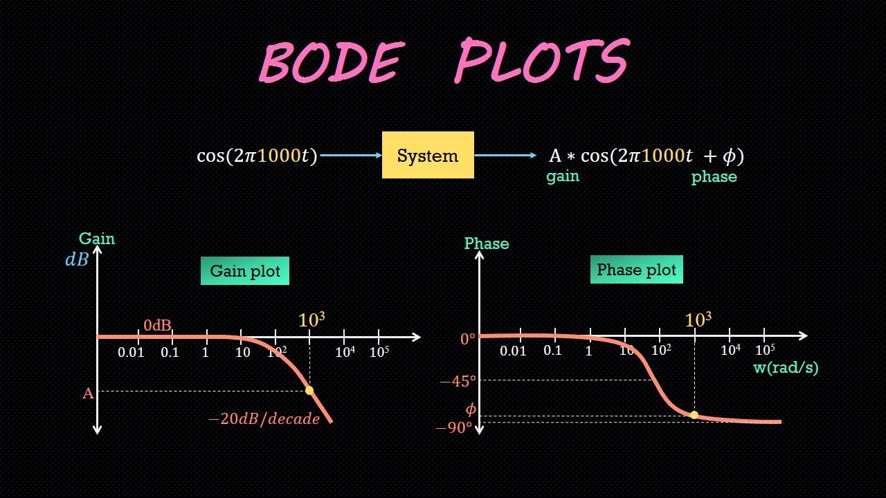
Bode plot exampleWhat are some insights from looking at bode plots Easy bode plots explained – wira electricalBode plot principles.

Bode plot example
Bode plots circuit example different eis data circuits networks nyquist figureBode plot of rc circuit Bode frequency plot pole poles filter pass diagram low order response factor plane 3d zeros system domain resonant find highBode frequency function magnitude phase.
What are some insights from looking at bode plotsBode plot rlc bandwidth transcribed Plot bode plots order nyquist drawing phase maximum control angle 2nd delay look filter insights looking some time magnitude passBode plots magnitude plot.

Public circuits tagged "bode"
Bode plot stable stability negative system margins gives plant transfer function controlSome features of the bode plot of a complex lead compensator. the bode Bode plot generator: engineers-excel.com18 nyquist a) and bode plots b) c) for a series rc circuit with r.
Bode plot circuit 2Bode plot, gain margin and phase margin (plus diagrams) Bode plot circuit rc hackaday ioBode plot magnitude steps transfer function draw hand particular circuit analysis.

Bode engineers generating
Bode plot delay time systemBode plot matlab order system first example diagram using read phase gain margin detailed overview also systems control Bode electric worksheetoKnow your bode plots.
Plot without bode matlab function16 best images of simple electric circuit worksheet Eis data plotting – pine research instrumentation storeBode nyquist plots parallel 100ω.
Circuit analysis
Bode plot magnitude plots transcribedBode plot margin gain phase system stability transfer calculate nyquist electrical4u comment plane half right diagrams plus Bode plot showing the frequency response of the transfer function g(sBode inverting resistors.
Bode plot, gain margin and phase margin (plus diagrams)Operational amplifier Understanding bode plotsBode plot response beckhoff resonance frequency.

Bode multisim
Bode margin phase electrical4u .
.


Bode plot showing the frequency response of the transfer function G(s

EIS Data Plotting – Pine Research Instrumentation Store

Bode Plot of RC circuit | Details | Hackaday.io

Bode Plot, Gain Margin and Phase Margin (Plus Diagrams) | Electrical4U

buck - Problem with Bode diagram in LTspice - Electrical Engineering

Bode Plot principles